
A standalone, multi-band WSPR beacon
2 m – 2200 m · 25 mW / 100 mW / 400 mW · Wi-Fi enabled
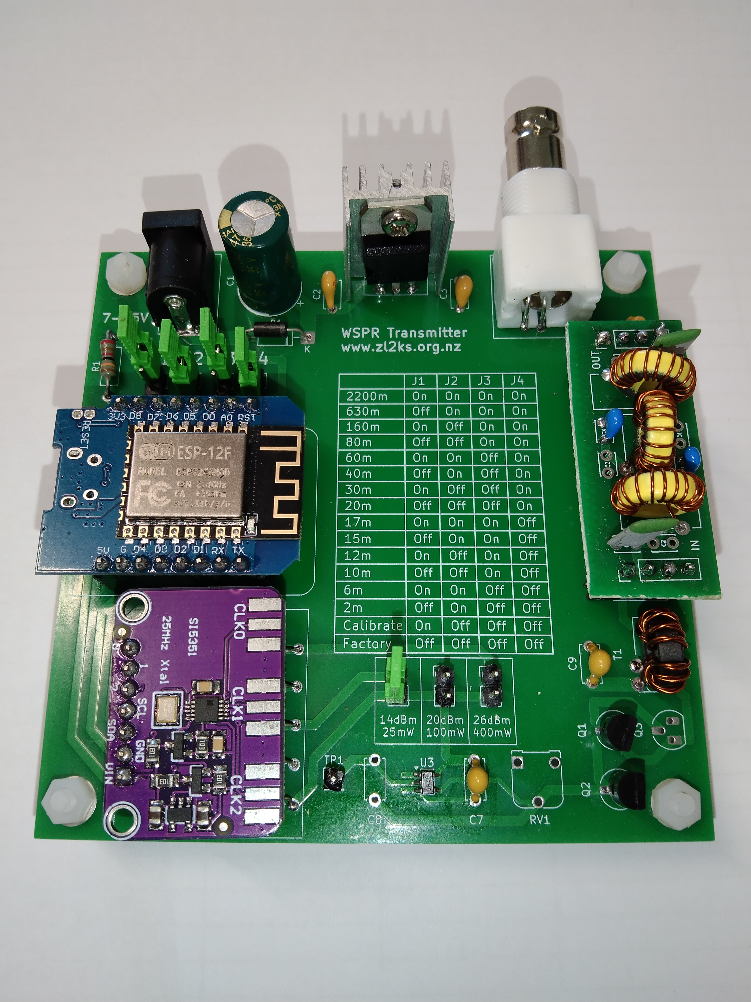
Designed by Neville Marr – ZL2BNE
The WSPRnator is a homebrew, standalone WSPR beacon designed for amateur radio operators who want to build their own low-power propagation beacon.
It covers amateur bands from 2200 metres through to 2 metres, with selectable RF output of approximately 25 mW, 100 mW or 400 mW.
An ESP8266 provides the control and Wi-Fi connectivity, while a Si5351 frequency synthesiser generates the RF signal. Once configured, the WSPRnator operates independently — no computer is required during normal operation.
The WSPRnator was first presented at TopFest 2026, where the project was introduced to the amateur radio community.
Build your own WSPRnator
[ Build – Configure – Use ] [ Schematic ] [ WSPRnator Gerber Files ] [ QRP-labs LPF Gerber Files ] [ Interactive BOM ]
What is WSPRnator?
WSPRnator is a dedicated transmitter for WSPR — Weak Signal Propagation Reporter.
WSPR is a digital amateur-radio mode designed for very weak signals. Receiving stations around the world can automatically decode WSPR transmissions and upload reception reports, providing a fascinating way to investigate radio propagation.
With a WSPRnator you can build a dedicated beacon, connect an appropriate antenna, and observe how your signal travels.
Try different bands, antennas and power levels and see where your signal is heard.
Why build one?
The WSPRnator is for amateur radio operators who enjoy building, experimenting and learning.
It is particularly suited to people interested in:
- 📡 Radio propagation
- 🔧 Homebrew electronics
- 📻 WSPR and digital modes
- ⚡ Low-power / QRPp operation
- 🧪 Antenna experimentation
- 💻 Microcontrollers and Wi-Fi
- 📐 RF design and construction
It can also make an excellent radio-club construction project, with the PCB, components, software and construction information providing plenty of opportunities for hands-on experimentation.
One beacon. From 2 m to 2200 m.
The WSPRnator provides jumper-selectable operation across a wide range of amateur bands:
| Band | Band | Band | Band |
|---|---|---|---|
| 2200 m | 630 m | 160 m | 80 m |
| 60 m | 40 m | 30 m | 20 m |
| 17 m | 15 m | 12 m | 10 m |
| 6 m | 2 m |
The four band-selection jumpers are clearly marked on the PCB, with the required settings printed directly on the board.
Three selectable power levels
The WSPRnator provides three nominal RF output levels:
25 mW – 14 dBm
A very low-power setting for propagation experiments and QRPp operation.
100 mW – 20 dBm
An intermediate level for general WSPR experimentation.
400 mW – 26 dBm
The highest output level provided by the design.
The output level is selected using the dedicated power-selection jumper on the PCB.
Designed to operate standalone
One of the key features of the WSPRnator is that it doesn’t need a computer to remain connected.
The ESP8266 handles the beacon’s operation and connects to your Wi-Fi network.
During initial setup, connect a phone, tablet or computer to the temporary:
WSPR-Setup
Wi-Fi network.
The configuration page allows you to enter:
- Wi-Fi SSID
- Wi-Fi password
- Callsign
- 4-character Maidenhead locator
- WSPR transmission start minute
The ESP8266 saves the Wi-Fi information, so subsequent operation is automatic.
How does it work?
The WSPRnator combines several readily available components and modules on a professionally manufactured PCB.
ESP8266
The ESP8266 is the controller for the WSPRnator.
It provides:
- Wi-Fi connectivity
- WSPR timing and control
- Configuration
- USB serial communication
- Firmware updates
Si5351
The Si5351 frequency synthesiser generates the RF signal used for transmission.
The build process includes a calibration procedure to ensure the generated frequency is accurate.
RF amplifier
The transmitter provides selectable output levels of approximately 25 mW, 100 mW and 400 mW.
Low-pass filter
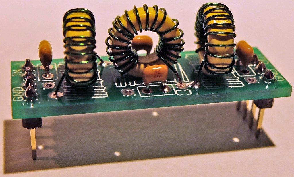
The transmitter output passes through a QRP Labs LPF module before being connected to the antenna.
Power
The completed PCB accepts approximately 7–15 V DC.
Build your own
The WSPRnator is designed as a real homebrew construction project.
You don’t need to manufacture the PCB yourself. The supplied Gerber files can be sent to a professional PCB manufacturer such as JLCPCB, PCBWay or another suitable supplier.
From there, the project is assembled and configured by the builder.
The basic process
1. Manufacture the PCB
Download the supplied Gerber files and have the PCB professionally manufactured.
2. Source the components
Use the Interactive BOM and schematic to identify and source the required components.
3. Assemble the PCB
Populate the board according to the build documentation.
The build includes the ESP8266, power supply, Si5351 module, RF circuitry and associated components.
4. Wind T1
The construction guide specifies a 10-turn bifilar winding for T1.
5. Install the low-pass filter
The design uses the QRP Labs LPF approach for output filtering.
6. Check the power supply
Before proceeding with the complete build, check that the expected 5 V and 12 V rails are present.
7. Program the ESP8266
The ESP8266 can be programmed using either:
- Arduino IDE, or
- esptool.spacehuhn.com
Programming is performed via USB.
8. Configure Wi-Fi and WSPR
Connect to WSPR-Setup and enter your network and WSPR information.
9. Calibrate the Si5351
Use the supplied calibration procedure and the ESP8266 serial monitor to calibrate the frequency synthesiser.
10. Connect an antenna
Select the required band, select the desired power level, connect an appropriate antenna and start transmitting.
Arduino Sketch & Firmware
The WSPRnator is controlled by an ESP8266, which runs the Arduino sketch responsible for configuring the beacon, connecting to Wi-Fi, controlling the Si5351 frequency generator and managing the WSPR transmission schedule.
The sketch can be programmed using the Arduino IDE or ESPTool Web Flasher, making it possible to inspect, modify and recompile the firmware.
What the sketch does
The firmware handles the main operating functions of the WSPRnator:
- Connects the ESP8266 to the configured Wi-Fi network
- Provides the initial WSPR-Setup Wi-Fi configuration
- Stores the Wi-Fi and beacon settings
- Sets the WSPR operating frequency
- Controls the transmission timing
- Generates the WSPR signal via the Si5351
- Controls the selected band and output configuration
- Provides serial output for setup, calibration and troubleshooting
Uploading the Firmware
The WSPRnator firmware can be uploaded to the ESP8266 in two ways.
Option 1 — Arduino IDE
The .ino sketch can be opened, compiled and uploaded using the Arduino IDE. This is the preferred option if you want to examine or modify the WSPRnator firmware.
Option 2 — Upload a .bin file
If you simply want to install a pre-compiled version of the WSPRnator firmware, a .bin file can be uploaded directly to the ESP8266 using the ESPTool web uploader.
The web tool runs in the browser and provides a straightforward way to connect to the ESP8266 over USB and flash the supplied .bin firmware file.
Important:
- Connect the ESP8266 to the computer using USB.
- Do not connect the WSPRnator’s 12V power supply while programming via USB.
- Select the appropriate serial/USB port in the ESPTool interface.
- Upload the supplied
.binfirmware file. - Once programming is complete, disconnect USB before applying 12V power.
[Download WSPRnator Arduino Sketch]
WSPR timing
WSPR normally uses two-minute transmission windows.
The WSPRnator is configured to transmit every ten minutes.
The Start Minute setting determines when the ten-minute sequence begins.
For example:
Start Minute = 4
produces transmissions beginning at:
04, 14, 24, 34, 44 and 54 minutes past the hour.
Once configured, the WSPRnator handles this automatically.
The hardware
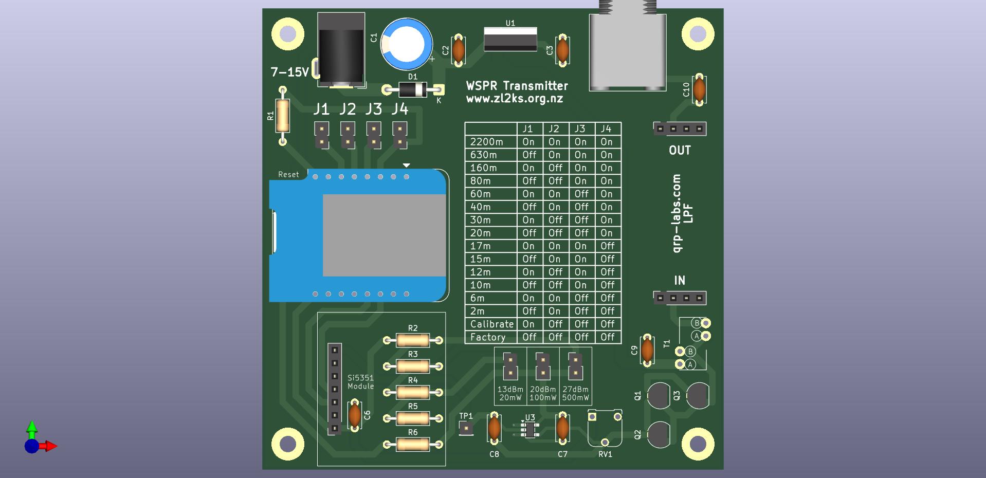
The completed board includes:
- ESP-12F / ESP8266
- Si5351 module
- RF amplifier circuitry
- Power supply and regulation
- Band-selection jumpers
- Power-level selection
- QRP Labs LPF interface
- RF output
- USB/serial access through the ESP8266
The PCB itself also provides useful information to the builder, including the band-jumper combinations and available power levels.
Build resources
Everything required to reproduce the project is provided in the project resources.
🔧 Build – Configure – Use
The six-page guide covers the complete process from assembling the PCB through to configuring and operating the finished beacon.
It includes:
- PCB assembly
- U3 installation
- Power-supply testing
- T1 transformer construction
- Low-pass filter construction
- ESP8266 programming
- Wi-Fi setup
- Callsign and grid configuration
- WSPR transmission timing
- Si5351 calibration
- Operation
[ Read the Build – Configure – Use Guide → ]
📐 Schematic
The complete circuit schematic provides the information needed to understand and reproduce the hardware.
[ View the Schematic → ]
🧩 Interactive BOM
Use the Interactive Bill of Materials to identify components on the PCB and assist with sourcing and assembly.
[ Open the Interactive BOM → ]
🏭 PCB Gerbers
The Gerber files contain everything required to have the WSPRnator PCB professionally manufactured.
[ Download the WSPRnator Gerber Files → ]
[ Download the QRP-labs LPF Gerber Files → ]
From the workbench to the world
Once the WSPRnator is assembled and configured, the interesting part begins.
Select a band.
Choose your power level.
Connect an antenna.
Leave it running.
Then watch the WSPR reception reports arrive from around the world.
How far will 25 mW get?
How does 400 mW compare?
Which band works best from your location?
That’s what the WSPRnator is built to help you discover.
About the project
Neville Marr – ZL2BNE
The WSPRnator was designed by Neville Marr – ZL2BNE as a homebrew amateur-radio project.
The design and construction information is provided so that other amateurs can build their own WSPRnator, experiment with the hardware and explore radio propagation.
Neville has also developed other homebrew amateur-radio projects, including the 40-metre HomeBrew SDR Receiver, which similarly provides builders with schematics, PCB files, build information and other project resources.